
DTRACK target calibration: practical tips for precise marker-based tracking
Phantom markers, axis alignment, SMARTTRACK workflows, and reference targets — proven tips for accurate DTRACK calibration in VR, metrology, and tool tracking.
Why target calibration makes the difference
In marker-based optical motion tracking, DTRACK delivers precise 6DOF data — but only when targets and reference bodies are calibrated cleanly. Errors in marker layout, visibility, or orientation directly affect stability and accuracy.
The following tips come from field practice: VR CAVEs and powerwalls, automotive engineering, robotics, and metrology. They help avoid common pitfalls and make calibrations reproducible.
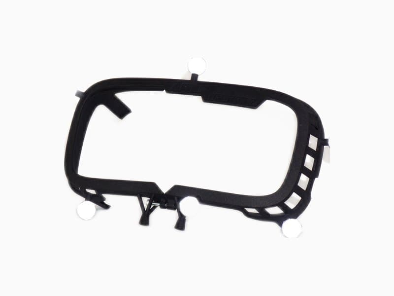
Phantom markers: set the origin where no marker can stay
Sometimes the origin of a calibration must sit exactly where no marker can remain during operation — but where one can be placed briefly during body calibration. Example: the weld spot of a welding gun.
Workflow:
- Attach markers only for configuration, then remove them.
- For a “clean” body calibration, use the marker first to set the origin (Set Origin).
- Remove the marker in the body adjustment afterwards.
If the desired point lies inside an object, place the phantom marker at an exact offset — e.g. 20 mm in front of the target position — and move it accordingly in software.
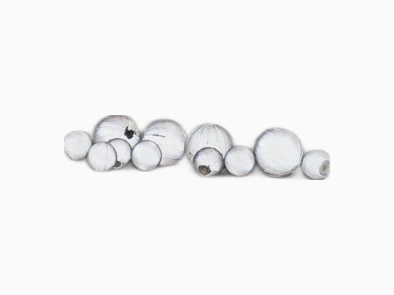
Passive markers appear bright in the IR image because their surface retroreflects — light returns almost parallel to the incident ray toward the camera. The physics behind this (glass beads, 3M material, spherical shape): Retroreflection — how glass beads make our tracking possible.
Align axes to markers: build a target for alignment
When a target has obvious spatial orientation, place markers so those directions are readable in the layout.
Seat buck example: Forward and sideways directions are often visible as aluminium profiles. Place one marker pair in the groove of a horizontal longitudinal profile and another in a horizontal cross profile. Then use Align to markers twice — once per axis — for full alignment.
Calibration helper frame: orient targets exactly
If targets must match a defined orientation exactly, fix them on a plate with additional markers for orientation, calibrate, then remove the helper markers.
Can be combined with a phantom marker for exact origin placement. Use distinctive calibration angles with care — they are easy to identify but not suitable for every geometry.
Calibrate in any direction, align later
Calibration requires all markers on a target to be visible. Tracking often needs only four markers to identify and three to continue tracking.
In practice: calibrate the target in a “wrong” orientation first, then use Align to room in body adjustment for the correct operating pose.
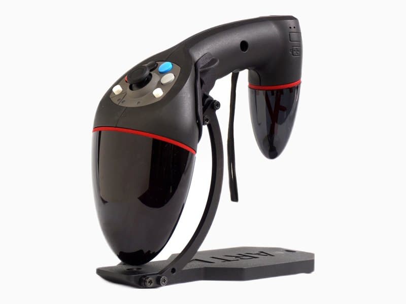
Especially helpful on SMARTTRACK3 — e.g. for a Flystick2: hold sideways toward the camera for calibration, then rotate into the working orientation.
Calibrate on another system and transfer data
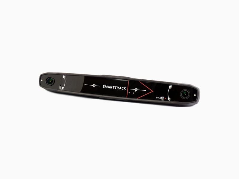
Some targets cannot be calibrated on a SMARTTRACK because they need multi-sided coverage. Calibrate in a multi-camera system (e.g. two cascaded SMARTTRACK3 units) and transfer the calibration data to the deployment system.
Calibrate with reduced intensity at the optimal spot
Tracking precision is best when camera rays cross at roughly 90° and distance is low.
For high-quality calibration:
- choose a pose where geometry is tracked optimally;
- reduce flash intensity so the rear of the target is not tracked — only the relevant marker side is captured ideally.
Better no marker than a badly seen one
Sometimes it helps to place markers where they are safely occluded from certain cameras — instead of being seen poorly by cameras that are often blocked during operation.
Especially for reference targets (or complete reference bodies): place markers where well-positioned cameras see them reliably — and not at all where floor or peripheral cameras would pick them up inconsistently.
Field example: Place a cardboard sheet under a reference target on top of a seat buck so floor cameras do not see it — experience from an automotive project.
Only small movement during calibration
Movement during calibration should avoid pixel effects, not trace large paths. Once you have a good calibration pose, a few centimetres of translation and small orientation changes are enough.
Next steps
- Marker physics: Retroreflection — how glass beads make our tracking possible
- Markers & targets: Product overview — markers and targets
- Software: DTRACK4 features and downloads
- Choose a camera: Camera comparison — SMARTTRACK3, ARTTRACK6/M, and AT7 side by side
- Plan your project: Tracking configurator or book an appointment